Tuesday, May 22, 2012

A3 - Parth Patel

1) Method Of Joints


2) Results of Analysis


3) Bridge Design Replicate
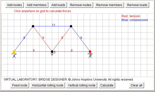

4) Hand Analysis Correspond to Bridge Designer

          For the hand analysis to correspond with the Bridge Designer, the length of the membranes need to be scaled equally. In Bridge Designer, the length is contained and scaled to 2 inches per graphical unit, while on the hand drawing we can draw membranes at any sizes. Therefore, Bridge Designer needs to scale their bridge so the forces correlate with the values calculated.


5) Bridge Designer for Knex Bridge
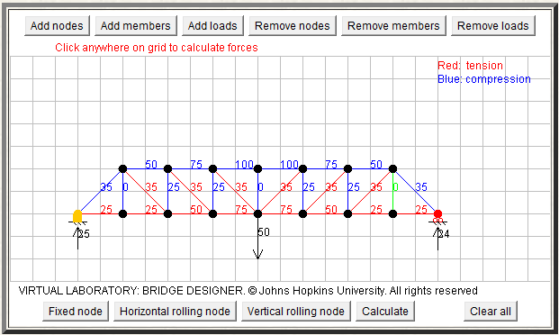

6) Final Analysis

          According to the Knex joints test page, it shows that it requires more force to remove a membrane from a 180 gusset plate as the number of membranes added to the gusset increases. Using the given average pull-out force for the different types of modes, such as one, two or three attached membranes, we can compare it with our Knex truss bridge. The online Bridge Designer has already computed the values of forces applied on each membrane of our bridge; so now we only need to identify the membranes close or far from the maximum limit of force. Than we could adjust those certain membranes to build a better cost to weight ratio bridge. For example, if a membrane if suffering force close to its maximum capacity, we can add more membranes in that region, such as to the gusset plates to make a stronger bridge. Similarly, if a membrane is suffering very few amounts of force, we could take the piece out and reduce the estimated bridge cost.

Week 8 - Analysis Process

      In my opinion, “Method of Joints” for analysis is not sufficient enough for a real bridge in a realistic situation. First of all, the load applied on a real bridge is different than the situation we considered for class where it only has vertical force. A real bridge will have force from all directions, for example the horizontal load from wind. Also the size and type of membranes included on a real bridge will contribute to how much load is actually felt on the joints. Another factor is the constant change of load applied on a real bridge, such as number of vehicles or weather patterns. Therefore, there will be a constant variation of forces applied on each membrane and joints.  In addition with “Method of Joints” I would also like to know the strengths of each membrane and joint so I could predict at which forces will the bridge collapse due to the specific parts. One more think I would like to analyze is the failure of the two 180 grooved gusset plates because they are found to be weak and caused our first bridge to easily collapse. 

       Last week in lab we discussed how to analyze the forces applied on a bridge by using the process called “Method of Joints.” With this method, students are able to learn how to compute tension or compression forces felt on each membrane of the truss bridge. This mathematical tool can help students compute the forces applied on their Knex bridges and make adjustments for a better result. For example, if certain membrane is experiencing a great amount of force, the best method is to make that area strong and compatible for the load applied. This week in class we will finish designing a truss bridge that will span over 36 feet and follows the new constrains. This will be the second bridge that the students will be testing in class. 

Tuesday, May 15, 2012

Week 7: Analysis Desires


One of the differences between WPBD software and Knex is the “Block box” answers. The “Block Box” provided with values associating with compression and tension of each membrane of the bridge design. These numeric values were very useful in terms of studying and understanding the strength and weakness in the design of the bridge. In addition, the software highlights the membranes that failed the bridge after each load testing. These were great beneficial features because it allowed us to analyze our bridge design effectively. As a result we were able to construct a serviceable bridge design that satisfied all the constraints and remained in low budget. Working with Knex would be more resourceful if there was a system to calculate the tension and compression of each membrane as it goes through the load testing. I would recommend using the VideoPoint software which can be used to record the testing and analyze the footage. VideoPoint with VideoPoint Capture allows you to gather position vs. time data of a QuickTime movie. The collected data can be viewed in a table and plotted to examine the design of the bridge.

During the previous week in class, our group was able to make little modification to the original bridge. While we modified our bridge, we were quickly able to come to a hypothesis that our grooved gusset plates and the long chord were worn-out from constant remodeling. From the testing we were able to conclude that our bridge design was very weak because it was only able to hold about 5 pounds. During the class discussion we were very interested by one of the groups who decided to design a bridge without any grooved gusset plates and produce good results. Therefore, we decided to redesign the bridge by completely replacing the grooved gusset plates with other connectors. This week in lab we will conducting more truss analysis and learning about the joint method and the importance of free body diagram.

Week 7: Analysis Desires

If we were able to get a analysis of the our KNEX bridge just like we got in WPBD, I would be able to tell what exactly is the problem with the 180 groove gussets. Like in WPBD, I wish I was able to see what the most strained or least strained pieces were, which pieces had the most tension in them, so that we knew how to change our bridge with a better perspective. Though we would not how to do further calculations with these numbers, since we have no prior background, but if given formula's, finding out more in depth analytical numbers would be greatly appreciated. But, for now we have to make best use of our eye, trying to watch each piece as more and more weight is put onto the load, if we are sucsessfully get three good angles at the bridge, we might have a good chance of seeing where out bridge exactly failed from.

Last week the entire class performed loading tests on our bridges. We came out with a lousy and pathetic 5 lbs. we partially knew that we would score low because of the 180 groove gusset plates that we used. Yes, they added a versatile part to our bridge, but in the end it was just too weak of a part. We did not just have once of them our every gusset plate on our bridge was that one, which amplified the instability of our bridge even more. This week we hope to construct an entirely new bridge that holds alot more than a measly 5 lbs.

Week 7 - Analysis Desires

West Point Bridge Design provided very useful feedback such as the tension force and compression force for every beam and gusset point. The numeric information helped students understand their bridges better; areas that are over strained or less strained. With this resource I was able to change the design around and try different methods to find the lowest cost to strength ratio. Unfortunately, Knex does not provide numeric feedback but allows student to visually see how the bridge fails. This allows students to observe the effects of different weights and points of the bridge where it collapses. However, with numeric information for the amounts of forces applied at various points of the bridge could help me understand better how the bridge fails. For example, if the tension on a certain beam is high, I would change the design on that area to prevent it from collapsing. Vise verse, if the tension on a certain beam is very low, I would try to parts out from that area so it can reduce the total estimated cost. Unfortunately, I have no previous idea or research for how to calculate these numeric values.   

Last week in lab we had spent a long period of time testing the bridges created by all the groups. My groups bridge resulted in a epic failure. It was completely unstable, unreliable, and only held a little over 5 pounds. My group had already anticipated a bad result before the test because we recently realized that the 180 groove gusset plates are extremely unreliable to use as connectors. The two combination of two 180 grooved gusset, which was used numerous times in our design, easily separated even without a lot of weight compressed on it. Unfortunately we didn’t have enough time to change our design and had to face the failure. However, my group has acquired significant knowledge from the failure to be able to build a better bridge. This week in lab we will learn how to analyze bridges and calculate numeric values, which will also help to design a stronger bridge for the week 8 test.  

Wednesday, May 9, 2012

Week 6 KNEX

Working with the KNEX for a week, I have come to the view that KNEX are alot better with building bridge. 
It gives you a wide range of connectors and different types of rods. With the KNEX we are actually able to test out out bridges, so the relativistic effects on a bridge are seen. the uneven weight distribution is put forth in front of you, unlike WPBD the full range of those defects are not seen. Here you are clearly able to see what connectors are bad and which are good. So that you know exactly which parts to replace and which to keep and where to change the structure of bridge if need be. Which WPBD did not show connector defects, it only showed uneven distribution in the rods. So, maybe changing a connector was not an option. Here it is, which also may keep cost down, since you are able to change a broader range of items. 

This week we will be testing the weight capacity of out bridges with sand, as well as the discussing and changes that might be needed to out bridge. We have done several modifications so far but our bridge still had about the same strucuture, a trapezoidal prism. This week we need to fix all of our connector issues that were presented to us last week. 

Tuesday, May 8, 2012

Week 6 - Knex Process


After working with the Knex for a week, I have noticed that my previous perspectives of the comparison between Knex and WPBD have slightly shifted. I have noticed that working with Knex gives you more options to design your bridge. Especially the connectors, WPBD is limited to one type of connector while Knex has variety of connectors. In addition, Knex consist of groove gussets that can be attached another groove gusset to strengthen the bridge. Some of the major flaw in the similarities and differences I had previously seen between Knex and WPDB programs is with testing the bridge. WPBD program provides a constant result because the bridge is being tested in a controlled testing field. The results from the Knex bridges can vary because the bridges are tested at an uncontrolled field. Therefore other factors can influence the end result of the bridge such as the position of the bridge and the placing of the weights on the bucket. Another discovery I made from working with the Knex was that the connectors and the chords starts to bend and becomes less stable, more we work with the Knex. Whereas, the joint and the membranes in WPBD programs remain stable and unchanged as they undergo more testing.

During the previous week in class, our group discussed about the design that will produce the most efficient bridge. For the rest of the class, we worked with the Knex to build one bridge as a team. We did several trial and error on our own and modified the design as went along. Although our bridge went through several modifications, the basic outline of the bridge remained as a trapezoidal prism. For the next week in class, we will be discussing the construction issues and conducting more Knex bridge testing.