Showing posts with label A3. Show all posts

Tuesday, May 22, 2012

A3-JACOB

1.Calculations of forces in  the truss members using the Method of Joints.
Truss Bridge That was used in Method of Joints

Calculation of Forces via Method of Joints (MOJ)  - 1

Calculation of Forces via Method of Joints (MOJ)  -  2


Labeled Diagram showing results of MOJ.

2.Results of the Analysis
From the truss analysis it can be concluded that the members connected to the center node will have tension and the members not connected to the center node will have compression.


 3.
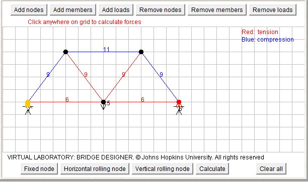
Bridge Designer Image Replicating MOJ
4.
The bridge designer is a very convenient method for calculating the tension and compression of each member in a Truss bridge design. The data collected from hand analysis and the online Bridge Designer is very similar. In order for both analysis to correspond, the length of the members and the angles must scale to each other. In Bridge Designer, each block represents 2 inches in length. Therefore, the ratio between the members must stay the same for the angles to stay the same. 


5.
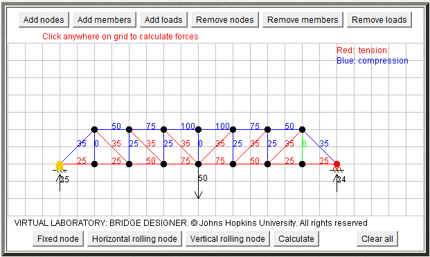
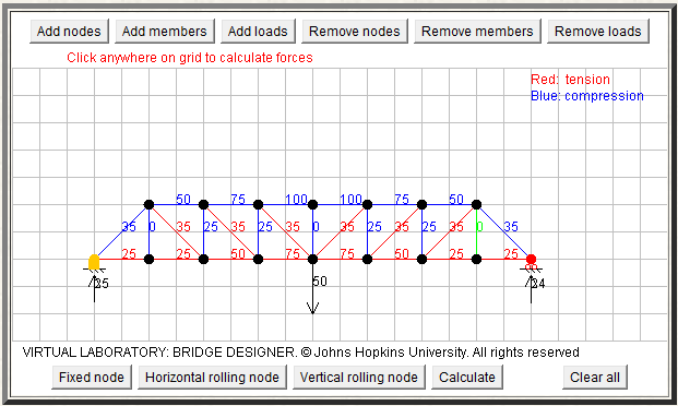
Bridge Designer Applied to our Knex Truss


6. How to Use Analysis to Improve the Design of Knex Bridge

Using the method of joints analysis, we can determine a value of the tension and compression of members of the bridge for a given load. The testing information about the K’NEX rods and K’NEX connectors provides the tensile pull-out force for various modes of connection. The web page displays three different modes of connections that contain different number of membranes connected to one connector. Analyzing the tensile pull-out force, it is evident that the pull0 out force increases with the number of membranes attached to the connectors. I was also ale to observe that the pull out-force greatly increased going from Mode 2 to Mode 3 rather than Mode 1 to Mode 2. This Tensile pull-out force table is useful in understanding that the how the number of membrane to connector ratio directly correlates with the stability of the bridge. From this information, our objective for this week would be detected the weakest connections and strengthening it by additional membranes.

A3 - Parth Patel

1) Method Of Joints


2) Results of Analysis


3) Bridge Design Replicate


4) Hand Analysis Correspond to Bridge Designer

          For the hand analysis to correspond with the Bridge Designer, the length of the membranes need to be scaled equally. In Bridge Designer, the length is contained and scaled to 2 inches per graphical unit, while on the hand drawing we can draw membranes at any sizes. Therefore, Bridge Designer needs to scale their bridge so the forces correlate with the values calculated.


5) Bridge Designer for Knex Bridge


6) Final Analysis

          According to the Knex joints test page, it shows that it requires more force to remove a membrane from a 180 gusset plate as the number of membranes added to the gusset increases. Using the given average pull-out force for the different types of modes, such as one, two or three attached membranes, we can compare it with our Knex truss bridge. The online Bridge Designer has already computed the values of forces applied on each membrane of our bridge; so now we only need to identify the membranes close or far from the maximum limit of force. Than we could adjust those certain membranes to build a better cost to weight ratio bridge. For example, if a membrane if suffering force close to its maximum capacity, we can add more membranes in that region, such as to the gusset plates to make a stronger bridge. Similarly, if a membrane is suffering very few amounts of force, we could take the piece out and reduce the estimated bridge cost.